Gavin's DIY Home Theatre (Hardcore)

Haha long story slowly write a bit every day. :grimacing:

Still have following sections… :sweat_smile:

  • Center speaker crossover design and tuning
  • ceiling hangar bass traps
  • ceiling baffle panels
  • surround speakers design and construction
  • room design and construction

Edit : And yet to be built stuff :

  • LR Mains speakers matching with center
  • SBA low bass absorption prototype on back wall
  • light reflection control
  • general acoustic treatment
  • Atmos speakers and mounting
  • woofer arrays for surround channels to run full range
  • Front wide speaker experiments
1 Like

Keep it coming

1 Like

Just recalled a few other references for push pull manifold subs. Can’t believe i left them out.
Did i mention i’m obsessed with bass and subwoofers? :laughing:

First, the Home Theater of the Decade - Hahn Theater. 24inch opposed manifold subs, with JBL M2 LCR.
https://www.avsforum.com/threads/home-theater-of-the-decade-the-hahn-theater.3111056/

I definitely took inspiration from the design of the subwoofer manifolds from the shoulders of these giants.

The Hahn screen wall with 6x IB Manifolds and LCR with JBL M2.

Keith Yates was the designer of the Hahn Theater. He apparently like the 24in manifold subs so much, he made it into a product.
https://keithyates.com/ubersub/

A CAD model of the Ubersub
image

And a render of an even more insane design, IB baffle wall with 10x uber sub manifolds.
image

1 Like

Damn…can’t wait for your dream home theater to complete so that everyone can pay you a visit. :grin:

2 Likes

Here’s another room build that also uses a IB low bass with pro sub midbass combo.

Also using JBL M2 monitors for LR mains.

This room was designed by Nyal Mellor. I learned a lot from his site, blog posts and case studies.

The JBL pro subs uses the 2269H subwoofer driver, which is another outstanding sub with unicorn specs.

Later I will sim it to show how close these various different drivers are. It is definitely a case of ‘convergent evolution’.

These are the unicorn pro subs with parameters that are optimised for low bass. Nero 15 (red), JBL 2269H (blue) and BMS 18N862 (green). Their response character is very similar. They are all in ~ 100-120L sealed cabs.

These will all hit very nicely in the balanced woofer range, just below 50hz with a massive efficiency boost from the high impedance peak. I have included a UM18 for comparison. It hits with authority right at the LFE 30hz range where all the low bass effects are focused. However, midbass and upper bass is rather uninspired.

i guess the takeaway here is if one craves the midbass slam and attack, a cost effective way is to get a pair of Nero 15 pro subs from the SB singapore distributors. Put them in a pair of 100L sealed boxes, and off you go.

1 Like

Resume the center channel build. After all that tricky part is sorted, remains to stuff the cabs, install drivers, wire up. Quite straightforward.

No secret sauce. I use the $2.90 ikea pillows for stuffing. Usually about 1lb/cuft. 2 cuft = 2 pillows. (don’t ask why using imperial, sometimes it is convenient :slightly_smiling_face:)
Well actually ikea stopped this model and I’m out of pillows for my further builds… :dizzy_face:

Another one of my ‘specials’. What’s the best electrical connection thru the cabinet walls? Is it rhodium plated solid copper? Soldered with high silver solder? Or perhaps gold plated.
In my simple reckoning, the best connector is no connector… :laughing: I drill a fitting hole and stuff the wire thru. Properly done sealed cabinets actually have a small hole drilled thru for pressure equalization, especially if the speakers are shipped by air…
Bam : nailed 2 birds there.

Now that I have adequately isolated the center speaker from the baffle wall, I have another conflicting requirement.

I actually need to seal the center speaker baffles against the wall somehow, to separate the air space between the back and front of the IB. Otherwise, the air will just leak back and forth, and may even have some turbulent or whistling noise.

So it is with a very heavy heart that I now set about compromising the wonderful sorbothane isolation, with sealing strips around the baffles.

I chose a 2 seal approach, stacked on each other. Thing with seals, while they may feel very soft when you press on it with a finger, that is just a small 1-2cm length. When you try to compress a full 2m length perimeter seal, the stiffness is actually very high.

Similar to calculating equivalent resistance in series or parallel. Resistance in series adds up, resistance in parallel is lower than any of the individual contributing resistors. If they are equal, then the resultant is halved.

Springs in Series and Parallel | Math & Physics Problems Wikia | Fandom
So I looked for the softest seals I can find. And then I stacked them, so that the resultant sealing forces are at least lower than any one of them alone.

The other benefit of this is a bit of labyrinth seal effect. This is used in gas turbine engines, they can’t actually have rubbing seals across the rotating parts. So the torturous path through the ‘labyrinth’ provides the sealing delta pressure.

Hahaha Hao siau only labyrinth seals. It’s the thought that counts right? :slightly_smiling_face: and the entertainment value…

I have a domed strip on the speaker baffle, and a foam strip on the wall.

So when I install the speaker, the dome profile pushes against foam strip…like so.

So that is how I’m sealing all the speakers mounted on the baffle wall. The 4 pieces of the center speaker, the 4 Low bass manifolds, and the 2 midbass subs.

How does it work in reality? Remarkably well actually. i’m sure there is some leakage past the IB.

I’ve read in those serious installer builds, that having some leakage past the IB baffle is actually a way to control the lowest room modal peak and decay. It is not a full seal. How convenient, i thought.

Actually, the part that comes and bites me is the sorbothane mounts. It is so effective at isolating the vibration because it is very soft. In vibration isolation theory, there is a transmission curve ( i learn this from sifu Marcus, *shoutout)

The way to read the curve, is if the system resonant frequency is much lower (here 1.0) than the working range (2 and upwards), there will be very low transmission across the isolators.

However, with a no holds barred ULF system, i can’t actually drop my center speaker isolation system resonant frequency below the passband. Even if it is at 5hz, we have content with 120dB at 5Hz. So what happens then?

Well from the curve, the system shakes like jello. I can verify the physics when testing Lone Survivor Load Up scene, with the chinooks and that (issit 14Hz) ULF pulsing… All my subs and the entire center channel speaker set are moving forward and back on the baffle wall, dancing like jello in tune with the Chinook blades.

Edit : not the speaker cones… Yes the sub cones are pumping air. But the entire baffle assembly with the drivers, are moving back and forth, on their soft sorbothane mounts.

So this is one thing i gotta fix. i have thought of a solution, and ordering some hardware to more securely fasten all the hardware onto the baffle wall, but still not with a ‘hard’ connection.

For vibration, everything must be ‘soft’… :laughing:

1 Like

Today I would like to share another ‘fail’ story.

Expectation:

Reality :

I actually spent quite a bit of effort installing the track lights, and led strip lights to back light the gear behind the screen.
The track lights had to be shifted 3 times, the DC brass power rails inside the tracks vibrate noisily to the slightest excitation.

The idea was to showcase the gear behind the screen, it seemed a cool idea and would also save a lot of explaining of what’s behind it. Unfortunately, it it not transparent enough…

If you can see the scalloped edges around the screen, that is actually a tightly stretched black spandex that I installed on the back of the AT fabric to improve the light rejection and dynamic contrast. I must say it has been very effective. I’m very happy with the brightness and dynamic image from AT screen. I think the PQ benefits outweighs the downside of not being able to showcase behind the screen haha.

In other news, the center speaker crossover parts have arrived.

Thx for sharing in such detail bro.

Enjoying reading your posts. Your technical knowledge is super power man! :scream:

Trying to understand all but some of it is really cheem! Salute u

3 Likes

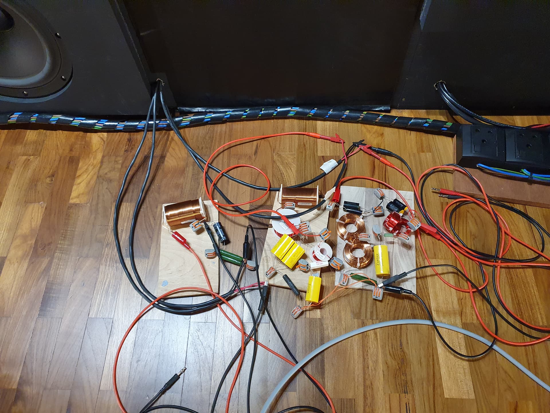
Good segue to start on the center speaker crossover design. The LCR design for this project is the single largest determining factor between success and failure.

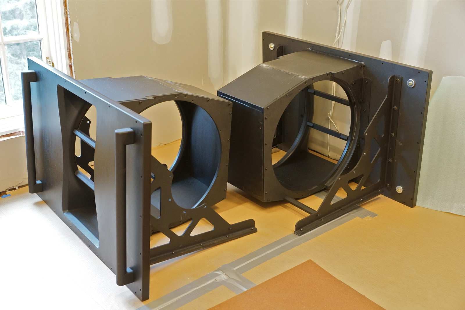
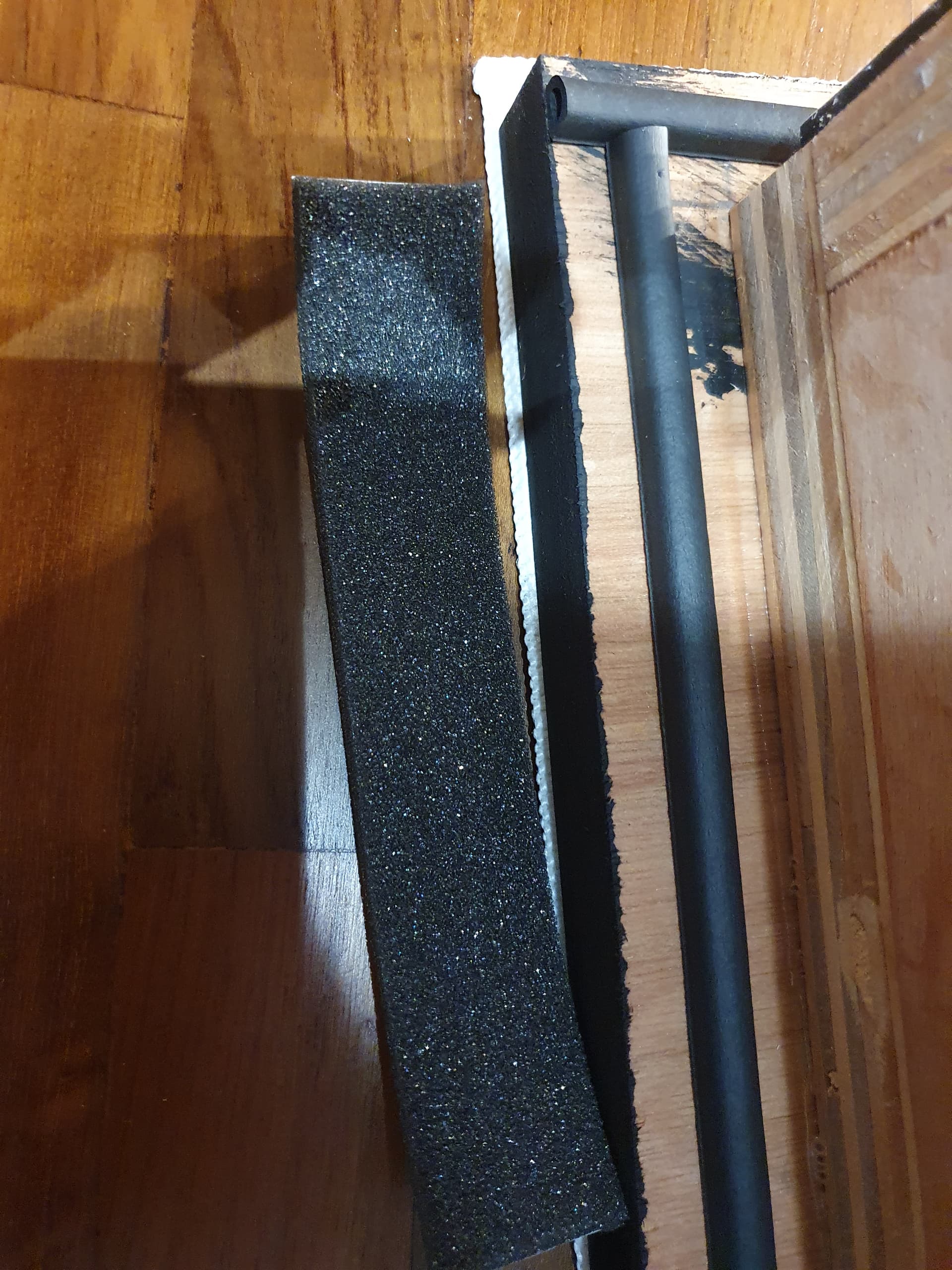
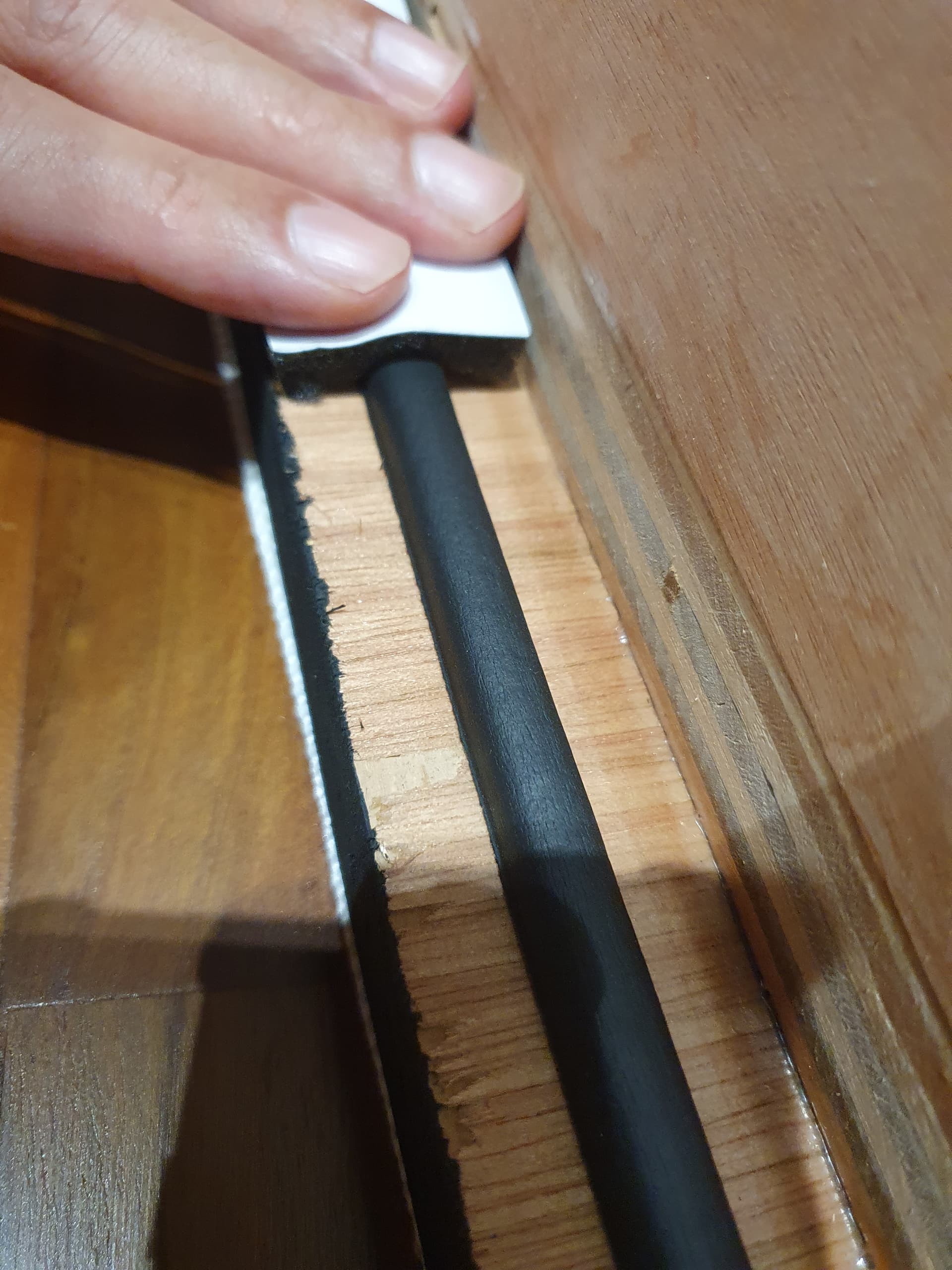
I tried to incorporate as much best practices as possible into the design. Front choosing the drivers, wg for directivity control, speaker cabinet vibration and external mounting vibration.

This is my biggest, most ambitious build using the fanciest parts. In a speaker, most critical part is the crossover design. One can do everything else absolutely stellar, and if the xo is lackluster, then the speaker will likely be mediocre as well.

In the early days of powered flight, there are the power people, who put the most powerful engines for maximum thrust. The Wilbur brothers focused on on flight controls. We know who won that race - power is nothing without control.

For me, the heart and soul of the speaker is the crossover, which together with the drivers, wg and baffle design, determine the directivity and power response.

Haha so without further ado.

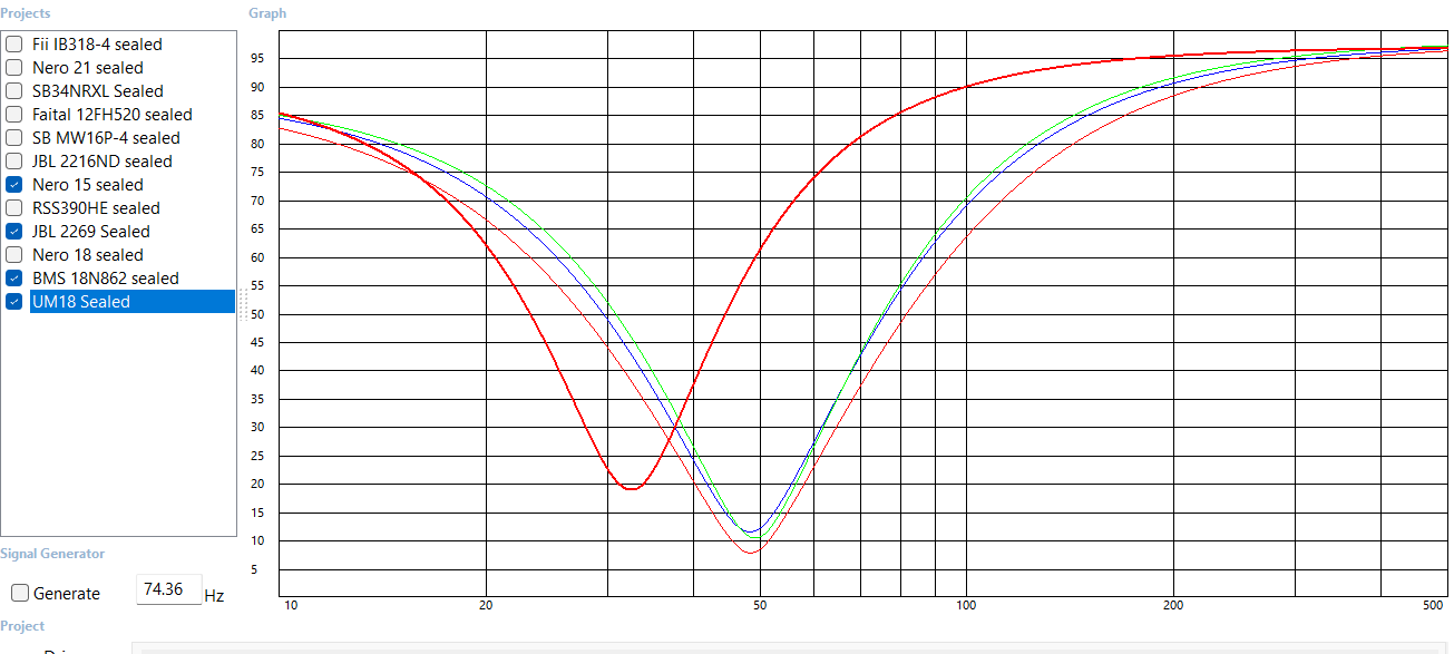
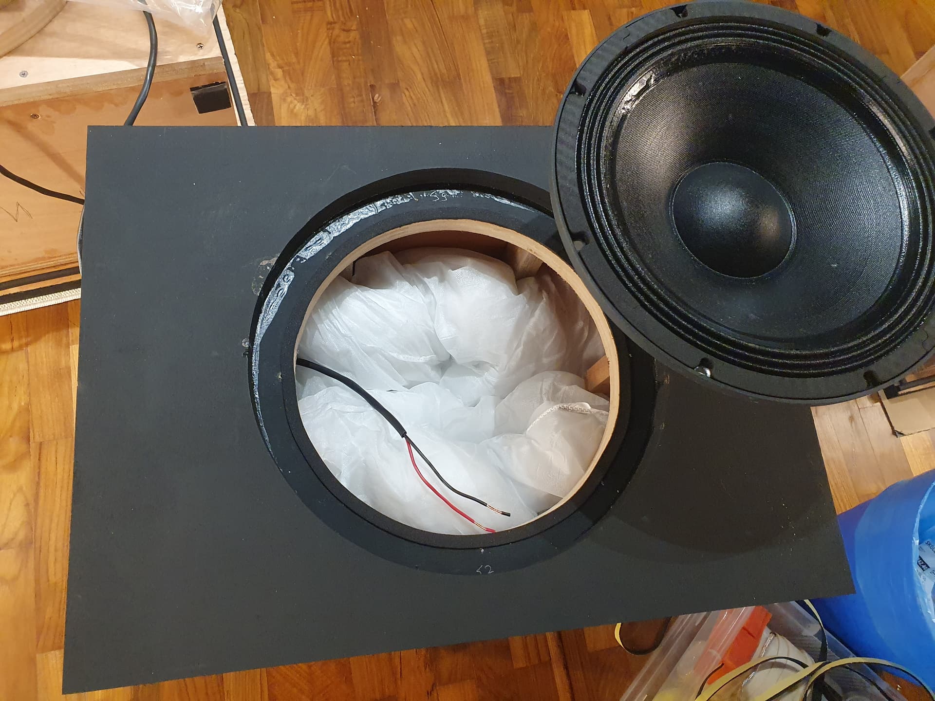
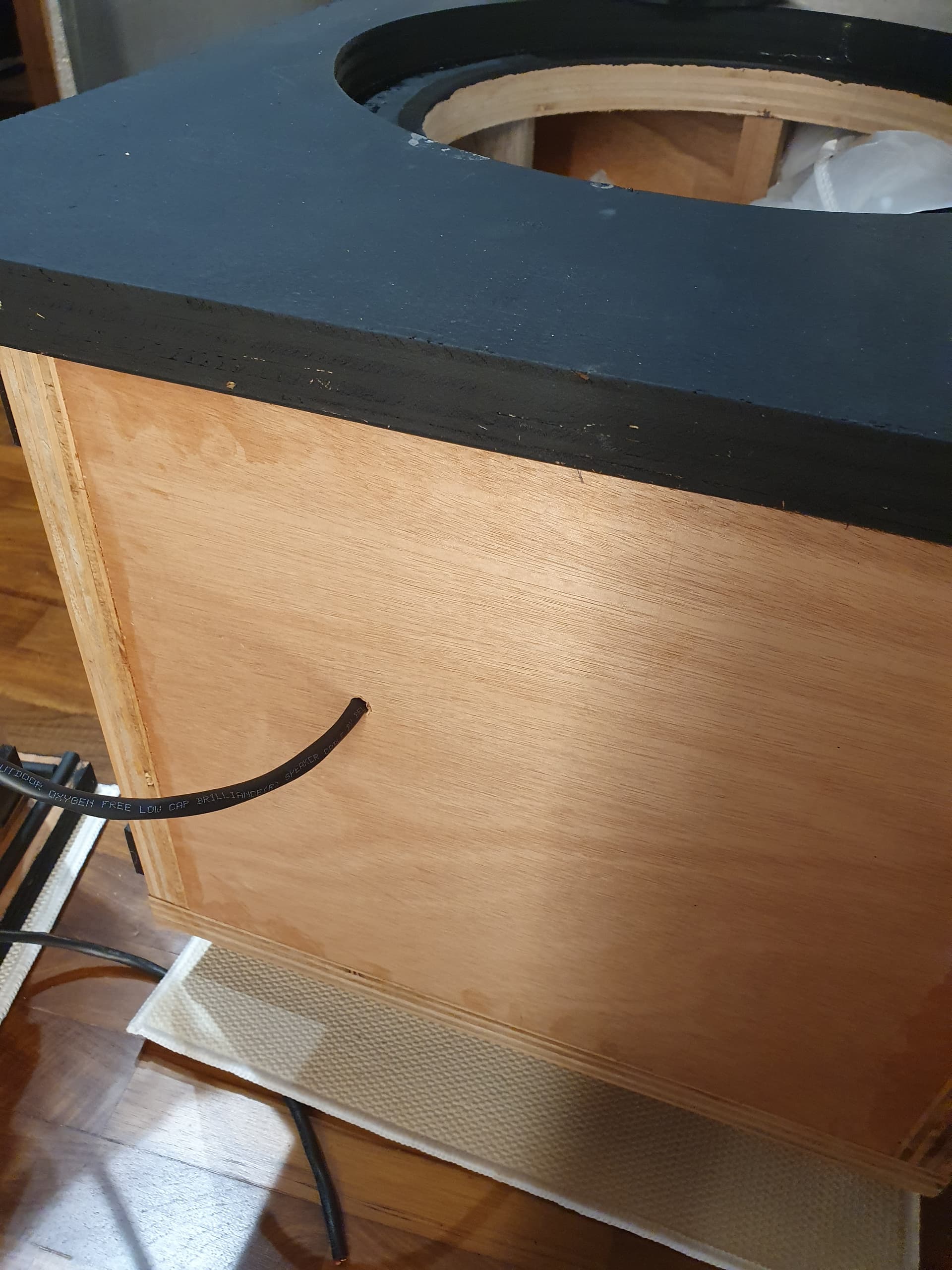
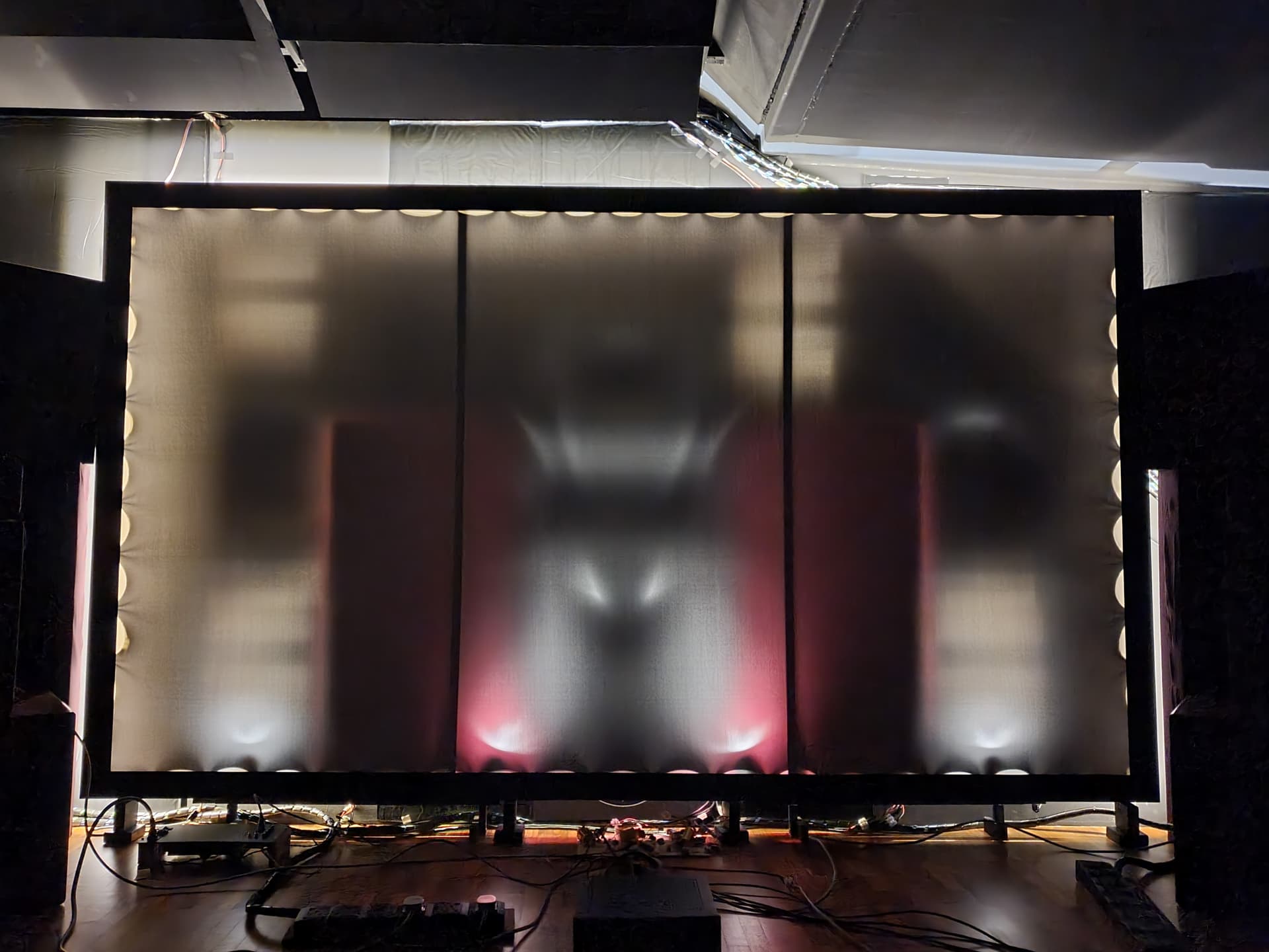
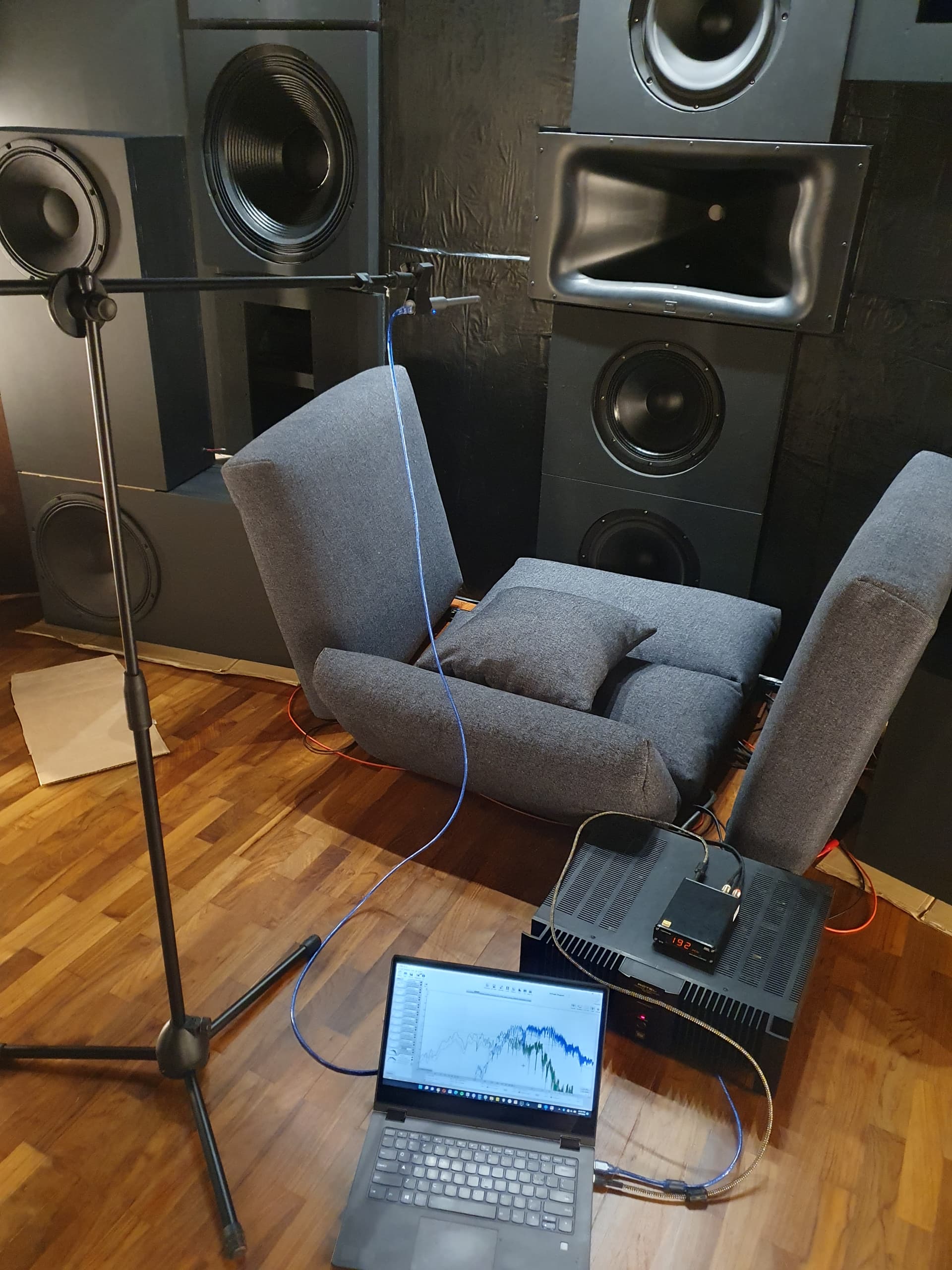
First impromptu measurement session just to see what I’m dealing with. Just grabbed some cushions from the sofa haha.

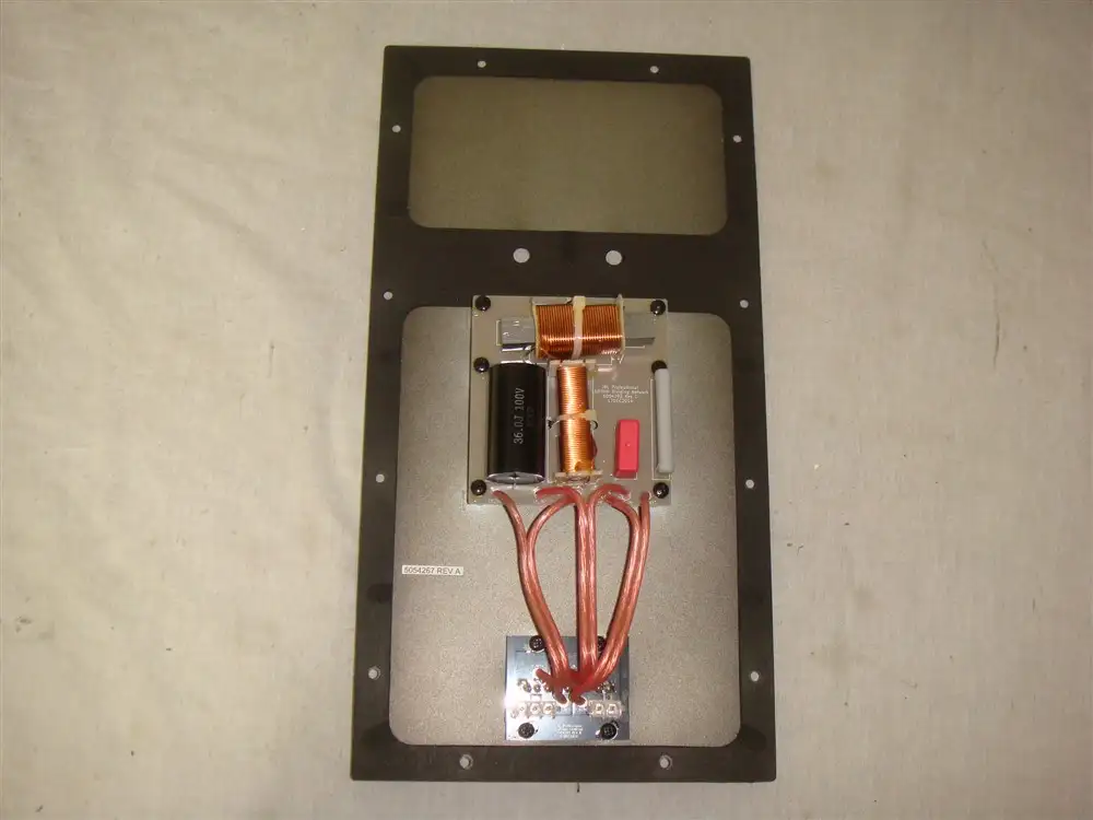
Before proceeding any further, it is worth talking about some differences in my xo design vs a commercial speaker.

The main difference - commercial designs are often done in anechoic environment, without /minimal influence of the room. This is because they will go into vastly different rooms, large and small, lively reflective or acoustically treated.

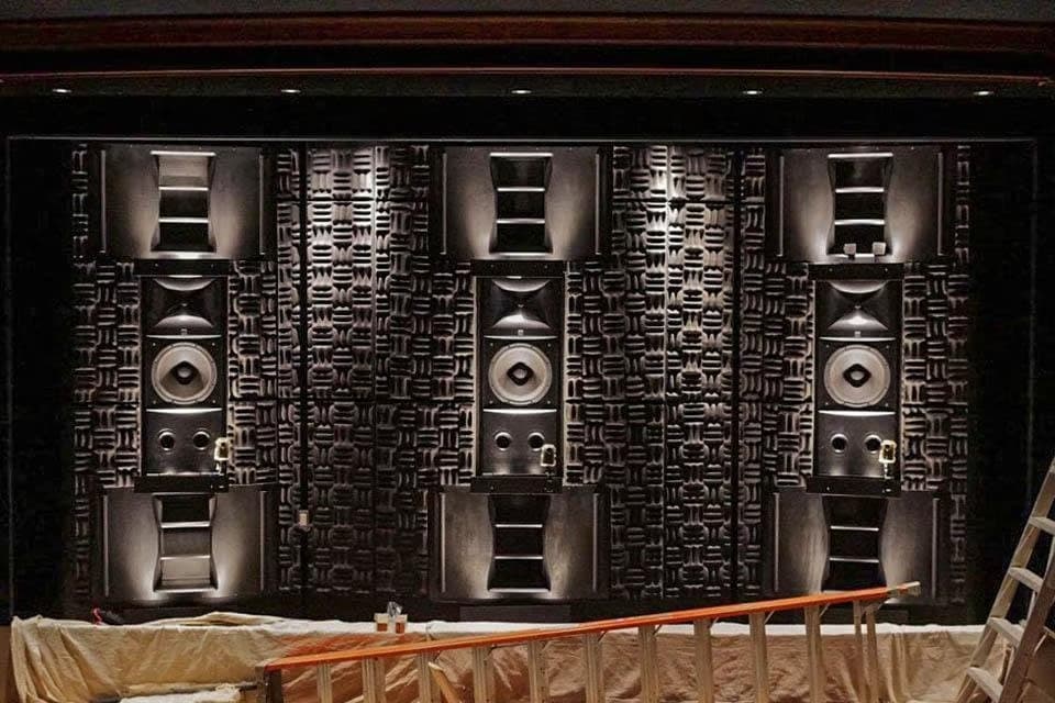
However, my speaker design is done in-situ. I know exactly where it is going, and what acoustical environment it will be on.

One main difference with baffle mounted /in wall /soffit mounted speakers is there is much less BSC - baffle step compensation needed.

Bookshelf or floorstanding speakers are designed for in room placement, and need between 3-5dB of BSC, which is basically shelving down the mids and highs to bring down the top, to balance the bottom.

Also, as my speakers will be used with room correction, I can also synergize between the crossover voicing, and the room EQ.

The other perspective is that active crossovers are very popular these days, with the availability of affordable dsp solutions like minidsp 2x4 HD. Some people believe this is the most ideal approach, that the active crossover is superior to a passive crossover.

I actually started my speaker design learning with active crossovers. It is a very powerful tool, one can literally play God with the response. But over time, I found from my experiences, that there are certain advantages with passive crossovers.

But before that, just some practical considerations for a 3 way active crossover for this single center speaker.

One would need -

-dsp platform, eg minidsp 2x4 HD

  • 1 rca - processor to minidsp
  • 3 rca - minidsp to power amp
  • 3 channels of power amps
  • 3 sets of speaker wires from amp to drivers

Now imagine multiply that by 3 for the front LCR…

But the biggest issue with an active crossover solution imo is the multiple DAC - ADC conversions. The signal goes thru DAC in the processor /AVR, then ADC into the minidsp for the dsp crossover, and out again via the DAC in minidsp. Far from ideal.

Bro, you have impedance curve and freq response for the tweeter?
Maybe specs link

For compression drivers, the response depends on the horn it is measured in…

Can see how it looks in the M2 WG.

Here’s the patent with more details of the D2 design. It is also a push push opposed diaphragm design.

Understand that the horn will change the freq response but data from the manufacturer on freq response and impedance curve can give very good baseline for simulation

After taking measurements of frequency response and impedance, it is time for some computer aided voodoo work.

This is one of many variations. But mainly the crossover frequency is there, about 800 - 900hz and upwards all handled by the big horn and compression driver. This is in contrast with most hifi speakers that crossover in the 2-3khz region.

After the crossover is modeled, it is time to build up a prototype. I find these connector clips to be very useful, neater compared to the crocodile clip wires that is commonly used.

It is still a big mess when hooked up to the speaker for listening tests! This is a big momentous and stressful occasion! The moment of truth, months of work leading to this moment.

One of the important verification step is to now measure the speaker response, and compare it to the simulated response. This is to see the agreement between what we think the passive crossover is doing in the simulation, vs what sound actually comes out of the speaker.

Gray line is simulated response with crossover, red is actual measured response with prototype crossover. I’m very very happy with the close agreement. It now gives me a solid starting point to tweak from. Whether it is to add, subtract.
I know where I’m going from, vs stabbing in the dark.

Edit : the differences in the low end, and general slight differences are due to slightly different mic position between the 2 measurements.
Also, in this measurements, I removed the LCR notch for the 10k peak, as it drops the too much. In the end I added it back after listening tests.

1 Like

A video from one of the first listening session. More tweaks and fine tuning followed after this.

With a HT system I knew that I always have the room correction to depend on for any lower range balance and correction.

The crossover phase tracking is most most important to get right, as that cannot be fixed in the EQ. Almost everything else can be left to EQ.

One can see an example of this in the JBL LSR 708i. It is the passive version that can be driven with a single amp channel, but still requires custom EQ filtering to achieve the final design sound.

One might gasp, but here’s the passive crossover in the 708i.

Here’s more details of how the passive crossover and active dsp combination works in the ASR review of the LSR 708i.

Part 1.

Part 2.

So in effect, what I’m doing is very similar, a simple (relatively) passive crossover, that is complemented by EQ from ARC.

There’s quite a bit of other details - devils in the details- but at a high level, that’s how I’m approaching my custom LCR for this build.

I have very good idea of the performance with the passive crossover, paying special attention to key areas. Then with ARC to back me up, I can have high confidence in the final outcome.

The proof is in the listening of course, and so far the center has been very good.

2 Likes